
Top 137+ Two way slab reinforcement details animation
beams are used in the column strip, distribute column strip moments between slab and beam. 3. Determine the area of steel required in the slab at critical sections for column and middle strips. 4. Select reinforcing bars for the slab and concentrate bars near the column, if necessary 5. Design beams if any, using procedures you learned in CIVL.

two way slab reinforcement details drawing pdf vansoffthewallwomen
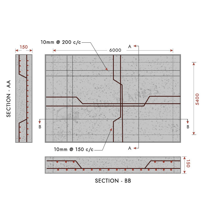
As can be seen from the figure-2 below, the tension reinforcement are 100% at the mid-span of the beam and slab, while it is curtailed at the distance of 0.1 L from the center of the support at end support and 0.2L at the intermediate support. L is the effective length of the beam and slab. The shear reinforcements are provided from the support.
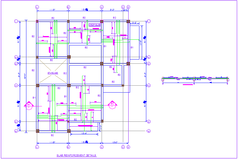
Construction view of slab reinforcement detail with section view for house dwg file Cadbull
a) Slab depth does not exceed 250mm when the steel grade is 250. b) Slab depth does not exceed 200 mm when the steel grade is 460. c) Slab reinforcement percentage less than 0.3% (100As/bd < 0.3%. When above a, b, and c conditions do not apply, bar spacing shall be limited as following Table (Table 28 of BS 8110 Part ) where the reinforcement.

Top 137+ Two way slab reinforcement details animation
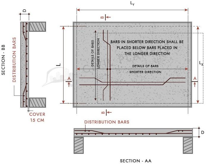
Two-way Slab Systems with Beams The location of the top reinforcement in the slab must be clearly indicated on the structural drawings where column-line beams are present. Because the minimum cover to the slab reinforcing bars is usually smaller than that of the beam reinforcing bars, the slab bars are typically placed above the top bars in the
Bar Bending Schedule For Slab One Way & Two Way Slabs
two way slab full detail explanation diagrams with sitebelow these links are our civil videos learn field work watch and subscribe for more videosbuilding d.
What Is Main Bar And Distribution Bar In Slab? [Civil
Two-Way Slabs 3 4. Direct Design Method "D.D.M" Before Discussion Of this Method, we have to study some concepts: 1. Limitations: 1. Three or more spans in each direction. 2. Variation in successive spans 33% ( . 3. LL 2 DL 4. Column offset 10% in each direction. 5. L/B 2. 6. For slabs on beams, for one panel. 2. Determination of Two way slab.

two way slab reinforcement details drawing pdf hippiesunandmooncanvaspainting
A rectangular reinforced concrete slab is simply-supported on two masonry walls 250 mm thick and 3.75 m apart. The slab has to carry a distributed permanent action of 1.0 kN/m2 (excluding slab self-weight) and a variable action of 3.0 kN/m2. The materials to be used are grade C25 concrete and grade 500 reinforcement. The slab is outside.

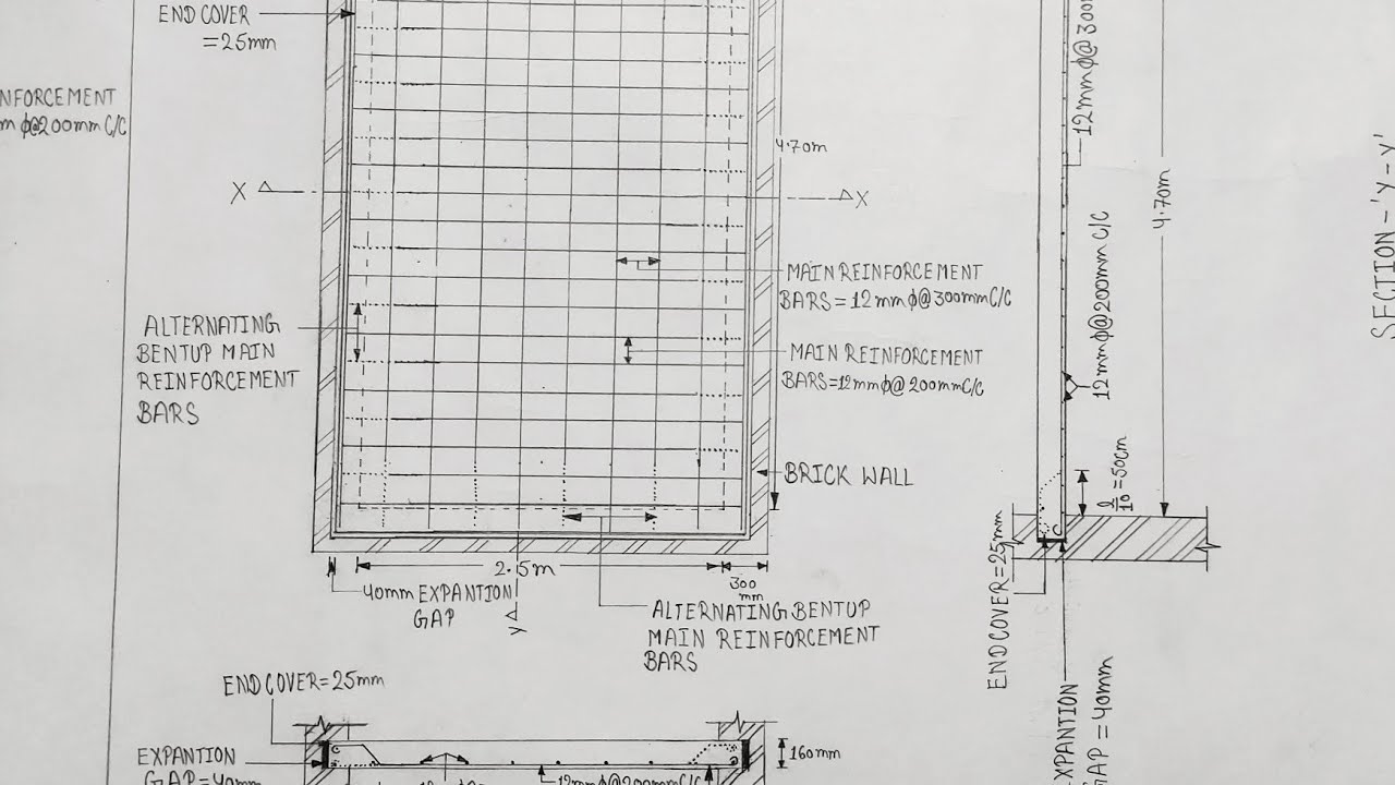
Complete manual calculation of Slab reinforcement details by using IS456 2000 code structural
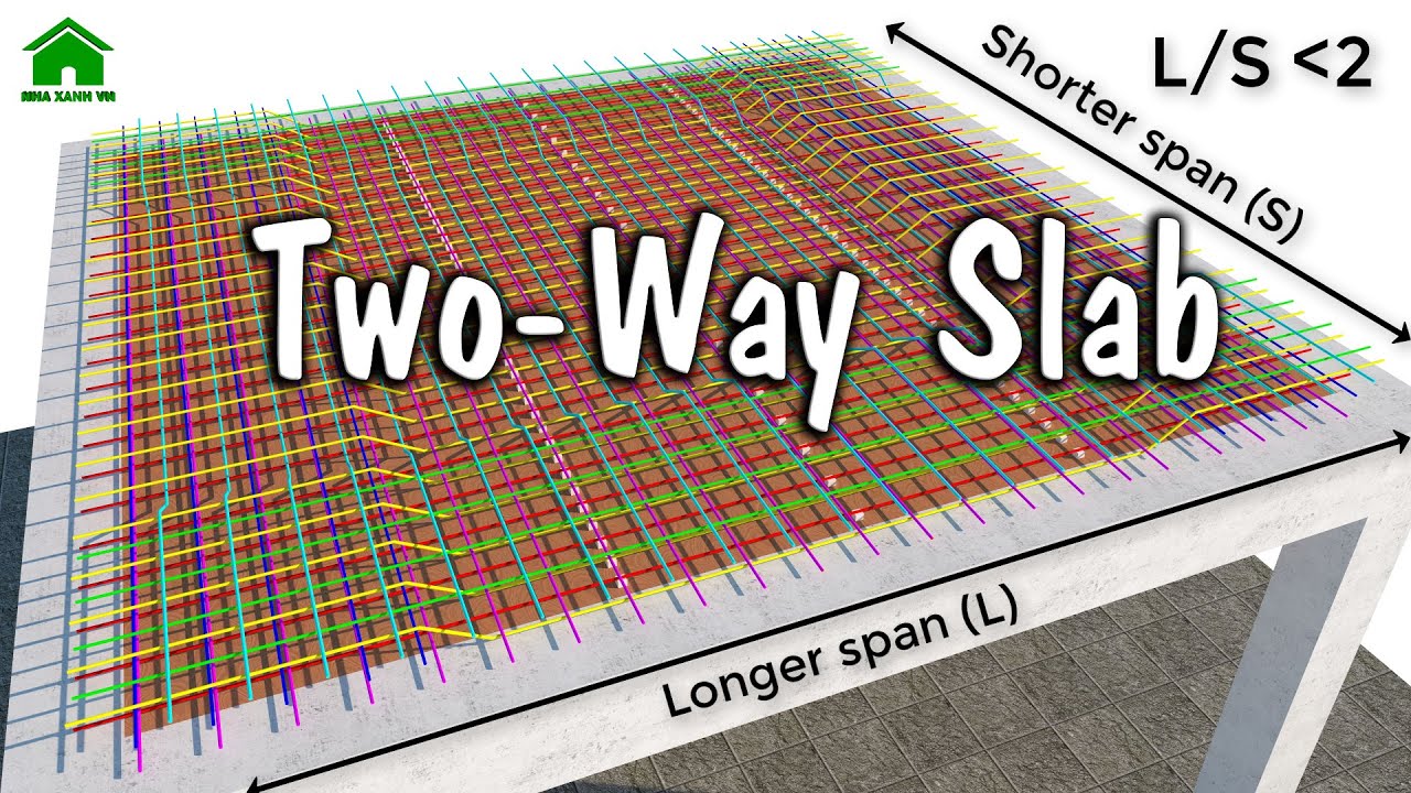
Common Methods of Detailing Two-Way Slab Reinforcement Two-way slabs are generally defined as suspended slabs whose ratio of long span to short span (bay length to width ratio) is less than two. Section 13.1.1 of ACI 318-111 identifies a two-way slab as a slab system designed for flexure in more than one direction. Normally, it is assumed

Two Way Slab Design Example Is 456 Pdf Design Talk
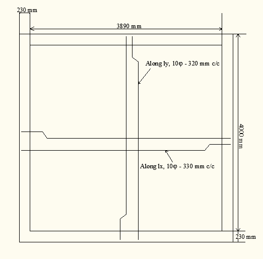
Q) Design a reinforced concrete slab for a room of clear dimension 4-meter x 5 meters. The slab is supported all around walls of width 300 mm. The slab has to carry a live load of 4 KN per meter square. and floor finishes 1 KN per meter square. Use M20 Concrete and 415 steel. assume corners are held down. Sketch the detail of reinforcement.

Update more than 72 beam reinforcement detail drawings super hot nhadathoangha.vn
The ACI Reinforced Concrete Design Handbook provides dozens of design examples of various reinforced concrete members, such as one- and two-way slabs, beams, columns, walls, diaphragms, footings, and retaining walls. For consistency, many of the numerical examples are based on a fictitious seven-story reinforced concrete building.
two way slab reinforcement details drawing pdf
Introduction: Detailing is often considered to be the preparation of working drawings showing the size and location of the reinforcement in a concrete structure. 3⁄4 Detailing involves thecommunication of the engineer's design to the contractors who build the structure.

Top 137+ Two way slab reinforcement details animation
Learn how to design and detail a two-way concrete floor slab with beams using CSA A.23.14 standard. This publication provides step-by-step guidance, examples, and tables for calculating the slab thickness, reinforcement, and deflection. Download the PDF for free and enhance your structural engineering skills.

two way slab reinforcement details drawing pdf lineartphotographypictures
Two-Way Concrete Floor Slab with Beams Design and Detailing - StructurePointThis pdf document provides a comprehensive overview of the design and detailing principles for two-way concrete floor slabs with beams, including reinforcement, deflection, punching shear, and fire resistance. It also includes examples and tables for practical applications. If you are an engineer or a student.
Aggregate more than 63 slab sketch super hot in.eteachers
All these two-way slab reinforcement details dwg will be used in any concrete beam slab floor system. These structural details dwg AutoCAD drawing download for concrete beam and slab system will help you to do any slab reinforcement detail drawing. Download Floor Slab Reinforcement Detail Sample #01; Download Floor Slab Reinforcement Detail.
Design of slab Two way slab design as per IS 456 2000 Learn Everything Civil and
The East (Section 5-5) and North (Section 3-3) walls are shown in cross section. The column footing and pier reinforcing bars are shown in schedules. In drawing wall elevations where footing steps occur, the detailer refers to the "Typical Stepped Footing" detail on the structural drawing and footing elevations on the plan view.

Two Way Slab Reinforcement Detailing
The design information that should be provided in the detailing of reinforced concrete slabs include: Layout and section drawings including details of holes and upstands, etc. Concrete grade and aggregate size (minimum standard 25/30 MPa and 20mm). Nominal cover to reinforcement and controlling design consideration, fire or durability (standard.